

All Posts By
pveng
Linear Multi-Body Analysis
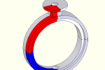
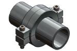
Connections such as flanges, tri-clamps and any other multi-body assemblies are analyzed using FEA. This example shows a Tri-Clamp connection under internal pressure and describes how FEA is used to provide insight into the interaction between components.
Riveted Vessels
This digester has been in use since 1926. Vessels built in that time period were typically constructed with riveted butt joints.

Reversed Dished Head
This reverse dished head could not be fabricated thick enough to meet the ASME VIII-1 rules. The chosen solution was to reinforce the head with ribs to prevent snap through. Various alternate methods of analysis are shown.
Pressure Analysis of a Flange
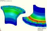
This basic sample illustrates how FEA is used to validate a flange design that cannot be calculated with standard VIII-1 Appendix 2 code rules due to the shape of its hub. Standard Appendix 2 loads are applied and assessed against the rules of ASME VIII-2 for full code compliance.
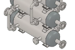
Frequency / Vibration Analysis
These stacked exchangers are analyzed using FEA and building code rules. FEA is used to determine the vibration frequency, which is put into building code rules to determine the base shear.
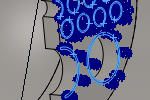
Simulating Heat Exchanger Tubes with Springs Post
Heat exchangers are often very large models. In order to simplify them for FEA we usually remove all of the tubes and replace them with simulated springs. This significantly reduces the complexity of the mesh.
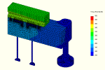
Thermal Analysis
FEA can calculate temperature profiles in single and multi-part models. From this, displacements and stresses are obtained. Here FEA is used to determine heat time and required power for an injection mold.
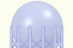
Reduce Your Mesh Time
Splitting a complex component into multiple smaller components can reduce the mesh time.
Solution for Long Mesh Time of Shells
When meshing shells using SolidWorks Simulation, the mesh gets up to 99% and then hangs for a very long time, sometimes for hours depending on the mesh size...
