

SolidWorks and Ansys Compared to ASME PTB-3

PVE-9128, Feb. 10, 2026, By: MPH/CBM/BTV
What is PTB-3
ASME problem sample manuals PTB-3 and PTB-4 are well kept secrets. The samples that used to be in the back of ASME VIII-1 in Appendix L have been changed, expanded and published as PTB-4. ASME VIII-2 was rewritten in 2007, and in 2010 it got its own new PTB-3 problem sample manual. PTB-3 contains examples with numerical results. Although meant more as an educational guide than a verification set, here we compare our own results in both Ansys and SolidWorks against published PTB-3 results.

The sample vessel design used in PTB-3 sample E5.2.1. All dimensions are in the corroded state. We ran this sample through Ansys and SolidWorks Simulation.
PTB-3 Example E5.2.1 and E5.3.2
PTB-3 example E5.2.1 “Elastic Stress Analysis” covers the correct use of stress linearization and provides numerical results. The same model is used for sample E5.3.2 “Elastic Analysis”. Here both are run.
[From E5.2.1] Evaluate the vessel top head and shell region for compliance with respect to the elastic stress analysis criteria for plastic collapse provided in [VIII-2] paragraph 5.2.2. Do not include the standard flanges or NPS 6 piping in the assessment for compliance to allowable stresses. Internal pressure is the only load that is to be considered. Relevant design data and geometry are provided below and in Figures E5.2.1-1 and E5.2.1-2.
In other words, analyse the head and a nozzle in the top of a pressure vessel to determine its acceptability against ASME code rules for FEA. The instructions for E5.3.2 are:
Evaluate the vessel top head and shell region given in Example Problem E5.2.1 for compliance with respect to the elastic and elastic-plastic local failure criteria provided in [VIII-2] paragraphs 5.3.2 and 5.3.3. The same model and material conditions were used as in Example Problem E5.2.1.

The pressure vessel head with nozzle as shown in PTB-3 sample E5.2.1 and also used for E5.3.2. The scope of analysis is limited to some of the shell, the head and the nozzle. The flange on the nozzle is modeled to allow loads to be applied, but is not included in the analysis.
Methods
This example provides enough dimensional and material information to attempt to duplicate the results. Exactly matching the published results is not possible because not all model geometry is given and some linearization locations are not exactly provided. The 8-node 2D Ansys structural element type PLANE183 was used to match the element type in PTB-3, however mesh sizes were missing. Where information exists, we replicated PTB-3 exactly. Where information is missing, we tried to get a model that looked similar to the one in the publication. Given these limitations, we hoped for results that match PTB-3 with less than 5% error.
The scope of study in Examples E5.2.1 and E5.3.2 is the shell, head and nozzle. These are symmetric about the centerline allowing a 2D axisymmetric analysis to be chosen by the authors. This reduced the complexity of the analysis and allows a refined mesh to be used. Most model dimensions were provided in drawings E5.2.1-1 and -2. We re-created the 2D model geometry in SolidWorks. Where model dimensions were not available, we made our model visually match the published drawing. A link to a drawing of our model is provided in the resources section below.
We used the same model in both Ansys and SolidWorks Simulation (SWS). We inferred the mesh size used by counting the number of elements in areas of known dimensions. We used this size of 0.015″ in both programs. The materials were modeled using the two different material moduli as outlined in PTB-3. The exact location of the change in modulus was not given, so we chose SCL #4 as the transition.
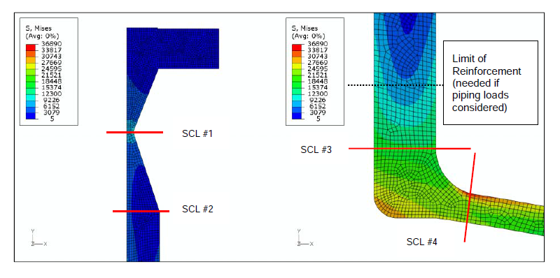
PTB-3 figure E5.2.1-10. Location of Stress Classification Lines (SCL) 1 thorough 4.

PTB-3 figure E5.2.1-11. Location of SCL 5 thorough 9. The exact location is not provided for 5 and 9.
We split the model at Stress Classification Line (SCL) locations 1-9 as shown in the PTB-3 figures E5.2.1-10 and E5.2.1-11. The exact location was not provided for SCL 5 and SCL 9. We attempted to visually match the publication. We used exactly the same location in both SWS and Ansys even if we could not exactly match PTB-3.
SCL Methods
Two issues stand in the way of getting good SCL data. 1) taking a SCL at a bad location, and 2) setting up the tool poorly. Getting good SCL locations is not always possible. Our article “ASME VIII-2 Permissible Cycle Life” discusses what to do when a good SCL is not possible. PTB-3 does not discuss the reason for the 9 SCL locations chosen. VIII-2 Annex 5-A.3 discusses the selection of SCLs. To avoid issues with improperly configured results when SCL tools some detail is provided here.
The SCL starts with stress data taken from the model. The data set is taken on a straight line from the inside to the outside of the model. The data is translated and rotated from global (or model) coordinates to local. When the SCL is on the X axis (like SCL #1 above) no rotation is required. The local direction 1-1 is the direction of the SCL. Stress in this direction is S11. Likewise S22 is perpendicular to the line on the plane of the SCL. S33 is perpendicular to the line out of plane. S12 is the shear stress in the plane of study. For 2D axisymmetric studies S13 and S23 are zero.

Rotation of the global to local stress components along the 11 axis of the SCL
The correct SCL components must be included to get the correct membrane and membrane + bending results in the SCL. The default settings in most SCL tools will not work for pressure vessel studies. In Ansys, the Linearized Equivalent Stress plot must have the Through-Thickness Bending Stress set to Ignore for a 2D axisymmetric study. For this 2D study, normal stress (S11) and shear stress (S21 = S12) are parallel to the SCL and do not contribute to SCL bending. Stresses S11 and S12 are removed from the tensors and the the invariants are calculated accordingly.

2D Axisymmetric SCL setup for Ansys
Results
PTB-3 does not discuss convergence of results or quality of the mesh. We used the Error plot built into SWS to determine if the model is adequately converged at the mesh size used since this is required under CSA B51 Annex J . Acceptable mesh errors in non discontinuity zones is 5%. Discontinuity areas often have higher errors. For this model the error is less than 1% except at SCL 1 at the base of the flange to nozzle weld discontinuity where it is an acceptable 5%. A similar plot was created in Ansys Mechanical by creating a User Defined Result with the Formula (SERR/ENERGYPOTENTIAL)*100.
We obtained displacement and stress plots from both SWS and Ansys that closely match the results published in PTB-3.

Table 1 – Results obtained by PVEng using SolidWorks Simulation and Ansys vs published results from PTB-3
A comparison of our SCL results from SWS and Ansys vs PTB-3 is presented in Table 1. Our results matched PTB-3 within 4% of full scale stresses. Given the assumptions we had to make in modelling this comparison, we consider these to be extremely good results. Our SWS results matched our Ansys results within 2.6%. We split the model at the SCL locations to remove sampling location errors between the two programs. The high convergence along with quadratic elements and the robustness of the SCL approach led to the Ansys and SWS results being consistent.
SWS and Ansys in daily use
We use SolidWorks Simulation and Ansys for a variety of design tasks in our office. The programs have different characteristics that lead them to be suitable for different applications.
Ansys allows a lot of control over the generated mesh and results data over SWS. This extra control also requires more effort. The Ansys quadrilateral mesh is expected to be more accurate than the SWS triangular mesh, but for this overrefined example, the differences turned out to be negligible. Ansys has the better results plots where screen updates happen much faster than SWS. And for non-linear analysis, Ansys provides results more often and is more stable than SWS.
Downloads the two reports for this validation exercise: Ansys and SolidWorks Simulation.
