

Quick Links
- 1 – Introduction
- 2 – Understanding the Problem Statement
- 3 – Methodology: A CFD Approach
- 4 – Importance of Key Parameters
- 5 – Comparing the CFD results with theory
- 6 – Key Findings
- 7 – Conclusion
Introduction
Thermal efficiency plays a crucial role in the performance of electrical heaters, impacting energy consumption, operational cost, and overall system effectiveness. Computational Fluid Dynamics (CFD) has become an indispensable tool for investigating how mechanical design and process parameters influence thermal efficiency. In this study, we analyze three key factors: velocity, addition of baffles, and baffle cut orientation. This article studies how these variables influence the thermal efficiency of an electrical heater.
Understanding the Problem Statement
The study aims to understand how changes in:
1. Velocity of the fluid flowing through the heater, 2. Presence of baffles, structural elements added to guide flow, 3. Baffle cut orientation, affect heat transfer efficiency. Thermal efficiency is directly tied to the heater’s ability to transfer energy to the fluid without excessive losses or hot spots.
Methodology: A CFD Approach
CFD simulations provide a detailed picture of fluid dynamics, heat transfer, and energy efficiency within the heater. The analysis follows the following steps:
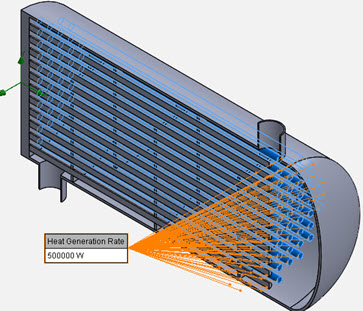
• Model Creation: A 3D geometry of the heater with and without baffles is developed in SolidWorks (see figure 1 below). • Meshing: The domain is discretized into finite volumes for numerical analysis (see figures 2a-2c below). The mesh is refined around the rods and baffles to better capture the high temperature gradients. • Boundary Conditions: Heating rate and water inlet velocity are specified (see figures 3a and 3b below) • Fluid properties: Water is used as the fluid that flows inside the electrical heater. The water mechanical properties are as shown in figures 4a-4c below.




Importance of Key Parameters
Velocity The velocity of the fluid determines the rate of heat transfer and the thermal gradient within the heater. • High velocity: Promotes better mixing, reducing thermal gradients but could lead to less residence time, potentially decreasing overall energy transfer. • Low velocity: Increases residence time but may result in stagnant zones, leading to inefficiencies. We have done two studies, one with the inlet velocity of 0.5m/s and the second with the inlet velocity of 1.5m/s. As show in the figures below, when the velocity is lower (0.5m/s), the fluid spends more time in contact with the heating elements and hence gets warmer. The outlet temperatures, the temperature fields, and the velocity fields are compared in the following figures.


Presence of Baffles Baffles act as flow control mechanisms, enhancing heat transfer by disrupting laminar flow and improving mixing. • They can eliminate dead zones and improve energy distribution. • However, excessive use of baffles can increase pressure drop and energy demand for pumping. To study the effect of the baffles on the thermal efficiency of the heater, we removed the baffles from the model and performed two studies: one with the inlet velocity of 0.5m/s and the second with the inlet velocity of 1.5m/s. As shown in the below figures, the removal of the baffles has reduced the outlet temperature by 4% for V=0.5m/s and by 1.5% for V=1.5m/s (decreasing the thermal efficiency of the heater). This effect will be more significant in the longer and larger heaters.


Cut Orientation of Baffles In this section we are going to change the cut orientation of the baffles from the horizontal cut (figure 13 below) to vertical cut and see how it will change the outlet temperature of water.


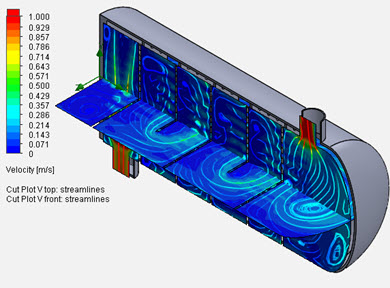
The outlet temperature of the water with inlet velocity of 1.5m/s and the vertical baffle cut is 30.17°C (30.07°C with horizontal baffle cut). The outlet temperature of the water with inlet velocity of 0.5m/s and the vertical baffle cut is 49.98°C (49.85°C with horizontal baffle cut). There is a difference, but it is not a significant difference. It is worth studying this effect using a longer heater to see how the difference magnifies in a larger heater. We will perform that study in part two of this article.
Comparing the CFD results with theory
In this section we are going to compare the CFD results with what is calculated using the convection heat transfer equation (Q ?=hA?T). The following boundary/initial conditions are used in our study for the case of vertical cut baffle with V=0.5m/s: Q ?=500,000 W, T_in = 20°C, T_out = 49.98°C, The surface area of all the rods (obtained from SolidWorks) = 8.0239m^2 (figure 13 below). Replacing these values in the convection heat transfer equation, we calculate: h = 500,000/[8.0239*(49.98-20)]=2,078.5 w/m^2.K. Comparing this value with the theoretical value of 2,091 w/m^2.K, as calculated in figure 14 below, results in a 0.6% error.


Key Findings
Effect of Velocity • Optimal velocity range ensures balanced heat transfer without excessive pressure drop. • Beyond a critical point, further increasing velocity diminishes returns due to reduced residence time. Role of Baffles • Baffles enhance mixing and heat transfer but introduce a trade-off with increased pressure drop (figure 20 below). • Optimizing the number of baffles minimizes these drawbacks while maximizing energy efficiency. Practical Implications • Industrial Use: Understanding these parameters allows industries to optimize heater design for energy efficiency and performance. • Sustainability: Improved thermal efficiency reduces energy consumption and lowers the carbon footprint. • Cost Savings: Enhanced designs cut operational costs by minimizing energy wastage.


Conclusion
CFD analysis reveals the intricate interplay between process and geometric properties in influencing the thermal efficiency of electrical heaters. Adjusting velocity within optimal ranges, combined with baffle placement, can substantially improve performance. These insights guide engineers in designing more efficient systems, contributing to sustainable and cost-effective operations.
