

Thermal Energy Storage (TES) systems rely on effective flow distribution and thermal stratification to achieve efficient energy storage and retrieval. Perforated plates are commonly incorporated into TES tank designs to distribute incoming fluid and minimize flow disturbances that could negatively affect thermal stratification.
However, modeling these perforated plates presents a significant computational challenge. A typical industrial TES tank may contain more than 100,000 perforations per plate. Explicitly resolving each individual hole in a three-dimensional transient CFD model requires an extremely fine computational mesh, resulting in excessive computational demands and impractical simulation times.
To address this challenge, an equivalent porous media modeling approach is used, allowing perforated plates to be represented through their hydraulic resistance rather than their individual geometric features.
This case study demonstrates how a validated simplified CFD model can substantially reduce modeling complexity while maintaining accurate predictions of the overall thermal response.
Engineering Challenge
The primary challenge was to accurately simulate fluid flow and thermal behavior within a TES tank containing densely perforated flow distribution plates, without explicitly modeling every perforation.
Conventional CFD modeling requires sufficient mesh resolution to capture the flow through individual holes, including local acceleration, pressure losses, and downstream velocity disturbances.
For industrial-scale perforated plates, the number of computational cells needed to resolve these features can make transient simulations prohibitively expensive.
The engineering objective was therefore to develop a simplified numerical representation that could:
- Reproduce the hydraulic resistance of the actual perforated plates.
- Maintain accurate predictions of the TES tank’s overall thermal response.
- Reduce geometric complexity and computational mesh requirements
- Provide a practical modeling methodology for evaluating industrial TES tank designs.
Development of a Reference CFD Model
A simplified TES tank was modeled with explicitly resolved perforated plates to establish a reference solution for validating the porous media approach.
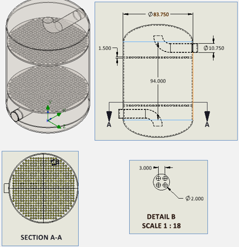
Figure 1 A sample TES tank is used for the validation
Inlet flowrate of 3 kg/s and pressure of 1 MPa are used for inlet and outlet respectively.
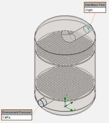
Figure 2 BCs
The mesh was refined at the fluid–solid interfaces and within the perforation holes to improve solution accuracy. This refinement ensures that the simulation accurately captures the flow disturbances caused by the perforations, as well as the velocity jets formed as the fluid exits the holes.
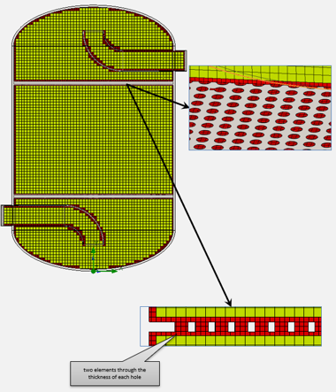
Figure 3 Mesh
A transient CFD simulation was performed to evaluate the fluid flow and thermal response within the tank.
The below plot illustrates the velocity field within the TES tank. The enlarged inset provides a detailed view of the flow through the perforations, with the velocity contours capped at 0.02 m/s to improve visualization of the flow distribution as the fluid passes through the holes.
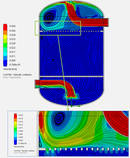
Figure 4 Velocity Field
The below plot shows the average temperature probed at the outlet nozzle as a function of time. The resulting outlet temperature history was used as the reference against which the equivalent porous media model would be evaluated.
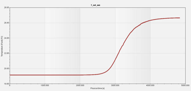
Figure 5 T_out as a function of time
Periodic Symmetry
To replace the perforated plates with an equivalent porous media model, the open area ratio and the pressure drop as a function of flow rate must first be determined.
A representative computational domain consisting of only a small number of perforations is analyzed using periodic boundary conditions (see figure 6 below). The periodic boundaries replicate an infinitely repeating perforation pattern, eliminating wall effects and ensuring that the predicted pressure drop is solely due to the resistance introduced by the perforations. By performing a series of CFD simulations at different flow rates, the pressure drop–flow rate relationship of the perforated plate is obtained. This relationship, together with the open area ratio, is then used to define the equivalent porous media model for the full TES tank simulation.
As shown in the screenshot below, periodic boundary conditions were applied in the X and Z directions, allowing a much smaller representative computational domain to be used while accurately reproducing the flow behavior of the full perforated plate.
The computational domain upstream and downstream of the perforated plate was made sufficiently long to ensure that the velocity profile was fully developed and uniform, and that the static pressure was stable at the locations where the pressure drop was evaluated.
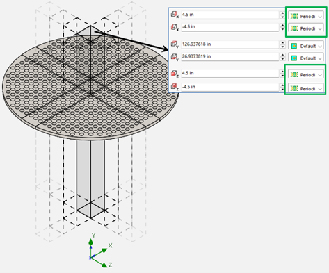
Figure 6 Periodic Boundary Condition
Parametric Study
A parametric study was performed by varying the mass flow rate from one-quarter of the nominal operating flow rate to four times the nominal operating flow rate to characterize the pressure drop over the expected operating range.
The mass flow rate was scaled according to the ratio between the area of the perforated plate represented in the periodic computational domain and the total area of the full-scale plate. As shown in figure 6 above, a 9 in × 9 in square section was used for the pressure-drop calculations. The corresponding area ratio is: 81/(PI()*81.75^2/4)=0.01543 (81.75in is the ID of the TES tank). So the equivalent mass flow rate is 3*0.01543=0.046296Kg/s (figure 7 below).
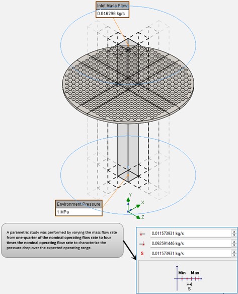
Figure 7 Parametric Study Parameters
Porous Media Definition
The results of the parametric study were used to determine the area-averaged pressures upstream and downstream of the perforated plate. The pressure drops across the plate were then calculated as the difference between these two average pressures. The resulting pressure drop versus flow rate was subsequently used as an input for defining the user-defined porous media model in the full TES tank CFD simulation (figure 8 below).
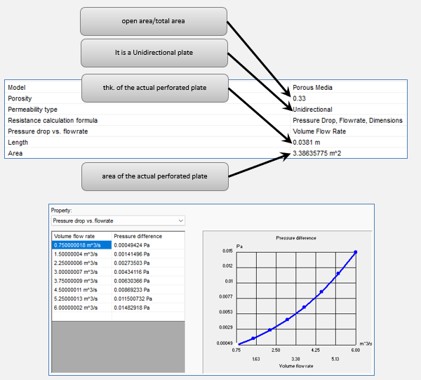
Figure 8 Porous Media
Equivalent Porous Media Model
The original perforated plates in the full TES tank model were then replaced with equivalent porous media regions.
This eliminated the need to explicitly resolve individual perforations, significantly simplifying the computational geometry and reducing the mesh resolution required near the plates.
The transient CFD simulation was repeated using the same operating conditions as the reference model.
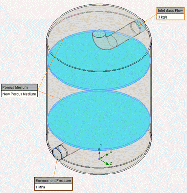
Figure 9 Model with Porous Media
The accuracy of the simplified model was evaluated by comparing the outlet temperature histories obtained from the two CFD simulations (figure 10 below):
- Reference model: Perforated plates with explicitly resolved holes.
- Simplified model: Perforated plates represented by equivalent porous media.
The comparison demonstrated close agreement between the two approaches throughout the simulated thermal transient.
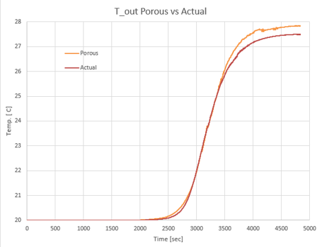
Figure 10 T_out Porous vs Actual
The maximum difference in predicted outlet temperature was less than 1.3%, indicating that the equivalent porous media approach accurately reproduced the overall thermal response of the reference TES tank for the investigated conditions (below plot).
Conclusion
This study demonstrates the effectiveness of combining detailed CFD analysis, periodic boundary conditions, and equivalent porous media modeling to simplify complex industrial flow simulations.
By characterizing the pressure-drop behavior of perforated plates and incorporating that resistance into a simplified CFD model, the overall thermal response of a TES tank was reproduced with less than 1.3% deviation in the predicted outlet temperature.
The methodology provides an efficient engineering approach for analyzing TES tanks and other industrial systems involving perforated flow distribution components.
The results also highlight the importance of validating simplified CFD models against higher-fidelity simulations before applying them to more complex engineering designs.
